A Charger That Lowers the Voltage
The socket in the wall of a house in Nepal supplies alternating current (a.c.) at about 220 V. A mobile phone battery could never take that much. It needs only a few volts. So how does a phone charge safely from a 220 V socket? The answer is hidden inside the charger.
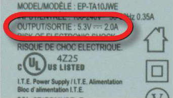
Every charger carries a small printed label called its voltage rating. The label below belongs to a mobile charger. Look at the line marked OUTPUT: it says 5.3 V. That is the voltage the charger gives to the phone. The charger is plugged into a 220 V a.c. supply, and a device fitted inside it brings those 220 V down to the 5.3 V the phone needs for charging.
What a Transformer Is
Some devices need the opposite job done. A microwave oven cooks food with microwaves, and producing microwaves needs about 2100 V. The socket gives only 220 V a.c., so a device inside the oven raises 220 V a.c. to 2100 V a.c. The charger lowers the voltage and the oven raises it, yet the device doing the job is the same kind in both. It is called a transformer.
Transformer: a device used to increase or decrease the voltage of alternating current.
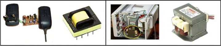
These two examples show two things. First, a transformer works only with alternating current: it takes a.c. in and gives a.c. out. Second, the same kind of device can make the voltage bigger or smaller. Which of the two happens depends on how the transformer is built.
| Device | Voltage it receives | Voltage it needs | What the transformer does |
| Mobile charger | 220 V a.c. | 5.3 V | Lowers the voltage |
| Microwave oven | 220 V a.c. | 2100 V a.c. | Raises the voltage |
Reading the Voltage Rating of a Device
Many other things at home and at school contain a transformer: a Wi-Fi router adaptor, a laptop adaptor, a television set-top box, an emergency light. Each carries a label with two important numbers. The input voltage rating is the voltage the device takes from the supply. The output voltage rating is the voltage it gives out. When the two are different, the device is changing the voltage, and a transformer is usually the part doing it.
Voltage rating: the voltage printed on a device, stating the input voltage it takes and the output voltage it gives.
Read only the label printed on the outside of a device. Never open a charger, an adaptor or a microwave oven, and never handle a plugged-in device with wet hands. The transformer of a microwave oven works at about 2100 V, which can kill.
Three Sections of Electricity Supply
Transformers are not only small parts inside gadgets. The biggest ones stand in power houses and substations, because using a.c. electricity involves three major sections: production, transmission and distribution.
- Production: a generator in a power house turns energy, such as the energy of falling water, into electrical energy.
- Transmission: the electricity is carried over long distances through high-voltage transmission lines.
- Distribution: near the places where it is used, the electricity is shared out through distribution lines to homes, schools and factories.
In Nepal, most electricity is produced at hydroelectric projects, where water held back by a dam turns the turbines.
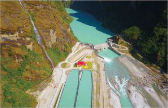
From there the electricity sets out on a long journey, and its voltage is changed twice on the way.
Transformers in Power Houses and Substations
The a.c. produced by the generator in a power house is first converted into a high voltage, for example 132 kV. One kilovolt (kV) is 1000 volts, so 132 kV is 132000 V. The electricity travels along the transmission line at this high voltage. Sending it at high voltage means a smaller current flows in the long wires, so less energy is wasted as heat on the way.
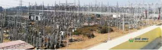
Nobody can use 132 kV in a house. So before the electricity is distributed, its voltage is reduced to a lower value, for example 220 V, at a load transmission centre called a substation. Transformers make both changes: the one at the power house raises the voltage, and the one at the substation lowers it.
Substation: a load transmission centre where the voltage of transmitted electricity is changed as required, for example reduced to 220 V before distribution.
Electricity produced by the power plants of Nepal can be sent within the country or outside it through high-voltage transmission lines. For example, the substation at Dhalkevar in Dhanusha transmits electricity at 400 kV.
Construction of a Transformer
A transformer inside a phone charger and one standing at a substation look very different. They differ in size and in some details of structure, but their working principle is the same, and so are their main parts.
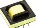
- Two coils, each made by wrapping thin insulated copper wire round many times.
- The two coils are not connected to each other by any wire.
- A soft iron core, on which both coils are wound.
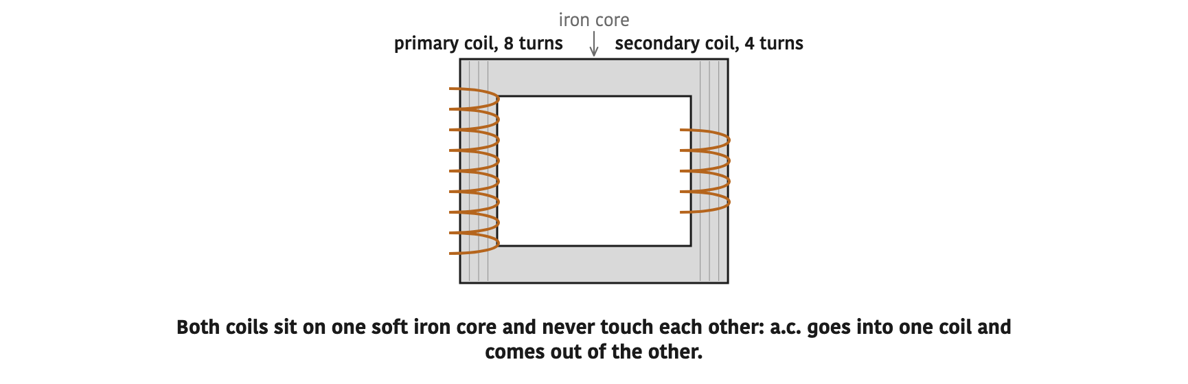
The insulation on the wire matters. It stops the turns of a coil from touching one another, and it stops current leaking from the coil into the core. Electricity does not pass from one coil to the other through a wire at all. It is carried across by the changing magnetism in the core, as the working principle shows.
Core Lamination
The core is not one solid lump of iron. It is built by stacking many thin iron sheets shaped like the letters E, U and I. Each sheet is coated with non-conductive paint, and the whole stack is tied into a single block with nuts and bolts. The E and I pieces are turned the opposite way on alternate layers, so the joints do not all fall in one line.
Core lamination: the process of building a transformer's core from many thin E, U and I shaped iron sheets, each coated with non-conductive paint, tied into a single block with nuts and bolts.
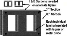
Why go to this trouble? The magnetic flux in the core keeps changing, and a changing flux induces currents in the iron of the core itself. In a solid core those currents would be large and would heat the core badly, wasting energy and possibly damaging the transformer. The thin insulated sheets break these currents up into tiny ones. In this way, laminating the core prevents excessive heating of the core.
The purpose of core lamination: to stop the core overheating because of the currents induced in it by the changing magnetic flux.
Working Principle: Mutual Induction
When an alternating current is sent through a coil, a magnetic field forms around it. Because the current keeps changing in size and direction, this magnetic field also changes periodically. The field reaches the nearby coil, so the magnetic intensity linked to that coil keeps changing too. Whenever the magnetic flux linked with a coil changes, an emf is induced in that coil. So an emf appears in the second coil even though no wire joins the two. The output current is drawn from the two ends of this second coil.
Mutual induction: the principle of inducing an emf in a coil by changing the current in the adjacent coil. The transformer is based on this principle.
This is why a transformer needs alternating current. A direct current (d.c.) flows steadily in one direction. Its magnetic field is set up once and then stays the same. With no change in the flux linked to the second coil, there is no mutual induction and no emf in it. That is why the voltage of d.c. cannot be changed by using a transformer.
A transformer does not work on the d.c. of a battery. A transformer connected to a battery gives no output voltage, because a steady current makes no changing flux.
Primary Coil and Secondary Coil
The two coils of a transformer are named after the job each one does.
Primary coil: the coil of a transformer into which alternating current is fed. It is the input coil.
Secondary coil: the coil of a transformer in which alternating current is induced. It is the output coil.
Each coil has its own number of turns of wire. The number of turns wound in the primary coil is called the primary turns, written \( N_p \). The number of turns wound in the secondary coil is called the secondary turns, written \( N_s \). To change the voltage of alternating current, a transformer is built with \( N_p \) and \( N_s \) different from each other.
The voltages have names too. The a.c. voltage sent to the primary coil is called the input voltage or primary voltage, written \( V_p \). The a.c. voltage received from the secondary coil is called the output voltage or secondary voltage, written \( V_s \).
| Quantity | Symbol | Meaning |
| Primary turns | \( N_p \) | Number of turns in the primary (input) coil |
| Secondary turns | \( N_s \) | Number of turns in the secondary (output) coil |
| Primary voltage | \( V_p \) | The a.c. voltage sent into the primary coil |
| Secondary voltage | \( V_s \) | The a.c. voltage taken from the secondary coil |
Apply these names to the charger. Its primary coil is connected to the 220 V socket, so \( V_p = 220 \text{ V} \). Its secondary coil supplies the phone, so \( V_s = 5.3 \text{ V} \). In the microwave oven, \( V_p = 220 \text{ V} \) and \( V_s = 2100 \text{ V} \).
Input side: primary coil, \( N_p \), \( V_p \). Output side: secondary coil, \( N_s \), \( V_s \). The small p always stands for primary and the small s always stands for secondary.
The full lesson is waiting for you
The notes are free to read in full. A free account opens the rest of the practice, and tracks your progress and confidence score for every subject. Presentations and videos need approval from Learn Yeti.