Joining Resistors and Ohm's Law
A real circuit rarely has just one resistor in it. A torch, the wiring of a house and a string of festival lights all have several bulbs or resistors working together. There are two basic ways to join them: in series and in parallel. The way they are joined decides the total resistance of the circuit, the current that flows through it and the potential difference across each resistor.
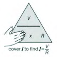
Every calculation in this topic rests on Ohm's law. As long as the physical condition of a conductor stays the same, the ratio of potential difference to current is constant: \( \frac{V}{I} = R \). So we can write \( V = IR \), \( I = \frac{V}{R} \) or \( R = \frac{V}{I} \), whichever we need. Potential difference V is measured in volts (V), current I in amperes (A) and resistance R in ohms (Ω).
What Two Bulbs Show
Two circuits can be built from two dry cells, two bulbs, an ammeter and a voltmeter. In the first, the bulbs sit one after the other on a single line of wire. In the second, each bulb gets its own path and the two sit side by side. The ammeter measures current and the voltmeter measures the potential difference between the two ends of the bulbs.
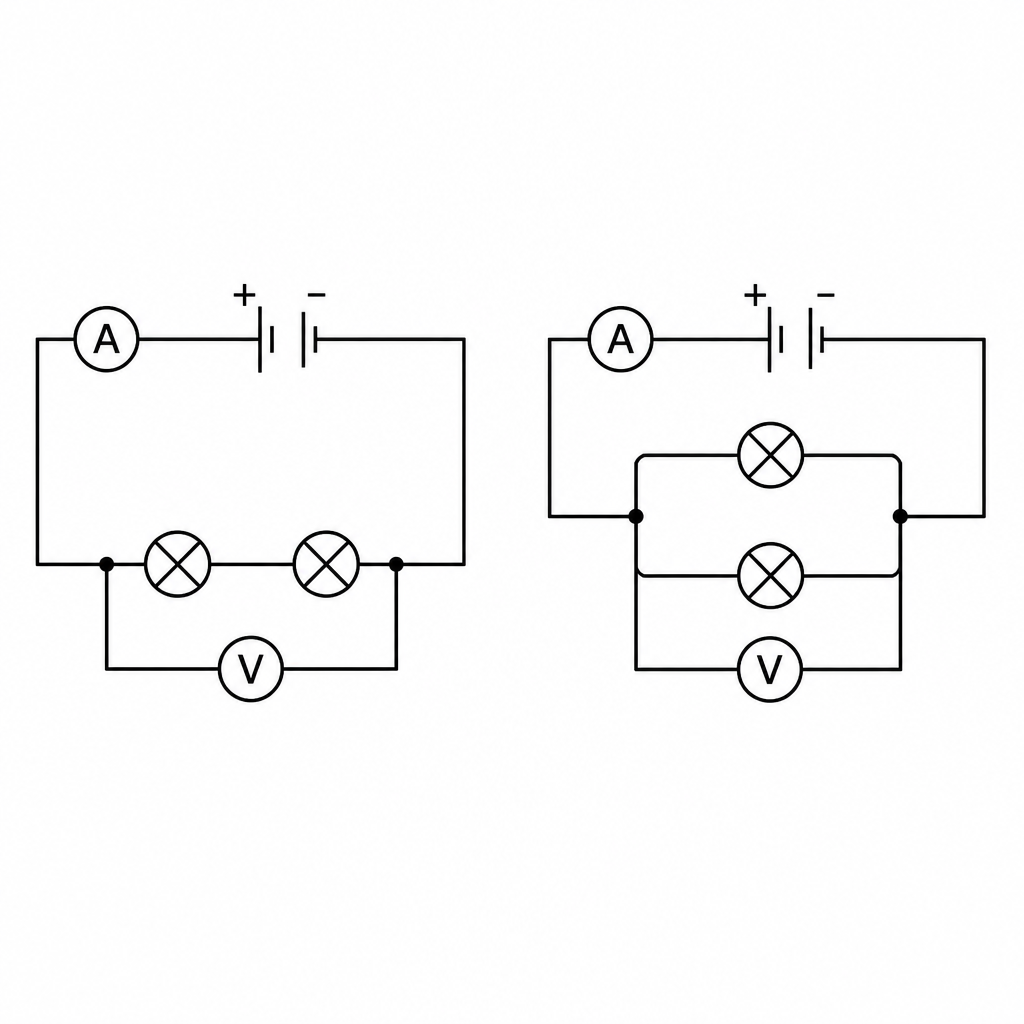
When the readings are taken, the two circuits behave very differently:
- With the bulbs one after the other, the same current flows through both bulbs, but their potential differences add up to the whole: \( V = V_1 + V_2 \).
- With the bulbs on separate paths, both bulbs have the same potential difference, but their currents add up to the current of the whole circuit: \( I = I_1 + I_2 \).
- Adding one more bulb to the one-after-the-other line makes every bulb glow more dimly.
- Adding one more bulb on its own separate path leaves the brightness of the bulbs almost unchanged.
The reason is resistance. A bulb added to the line is one more obstacle the same current must push through, so the current falls and the bulbs dim. A bulb added on a new path still receives the full potential difference of the cells, so its brightness does not drop. The two arrangements are studied one at a time below.
Series Combination of Resistors
Series combination: an arrangement in which resistors are joined end to end, one after another, and only the first and the last are connected to the source of electricity.
In a series combination the current has only one path. Whatever current passes through the first resistor must pass through the second and the third as well. The potential difference supplied by the source, however, is shared out among the resistors, and a resistor with a larger resistance takes a larger share.
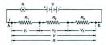
- Every resistor carries the same current I.
- The potential difference is divided among the resistors.
- If any one resistor fails, the circuit is broken and all the others stop working.
- Each resistor cannot be given its own switch.
- This arrangement is used in decorative lights such as those hung for Deepawali.
Total Resistance in Series
Take three resistors \( R_1 \), \( R_2 \) and \( R_3 \) joined in series. Let the potential differences across them be \( V_1 \), \( V_2 \) and \( V_3 \), let the common current be I, and let R be the total resistance of the three. The total resistance is the resistance of a single resistor that could replace all three without changing the current.
Total (equivalent) resistance: the resistance of one single resistor that would draw the same current from the same source as the whole group of resistors.
Step 1: The potential difference is shared among the three resistors, so:
\[ V = V_1 + V_2 + V_3 \]
Step 2: Using Ohm's law, and remembering the current I is the same in every resistor, substitute \( V = IR \), \( V_1 = IR_1 \), \( V_2 = IR_2 \) and \( V_3 = IR_3 \):
\[ IR = IR_1 + IR_2 + IR_3 \]
Step 3: Dividing both sides by the common current I:
\[ R = R_1 + R_2 + R_3 \]
In series, the total resistance equals the sum of the separate resistances. So the total is always larger than even the largest resistor in the group.
Parallel Combination of Resistors
Parallel combination: an arrangement in which two or more resistors are each connected separately across the source, with one end of every resistor joined at one point and the other end of every resistor joined at a second point.
In a parallel combination every resistor has the same potential difference V across it, because all their ends meet at the same two points. Each resistor, though, has its own path, so the main current splits into branches at the junction. The branch with the smaller resistance carries the larger current.
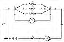
- Every resistor has the same potential difference V across it.
- The current divides among the resistors.
- If one resistor fails, current keeps flowing through the others and they can still be used.
- Each resistor can have its own switch.
- The electrical loads in our homes, such as lights, fans and televisions, are connected in parallel.
Total Resistance in Parallel
Now take three resistors \( R_1 \), \( R_2 \) and \( R_3 \) joined in parallel. Let the branch currents be \( I_1 \), \( I_2 \) and \( I_3 \), let the shared potential difference be V, let the main current be I, and let R be the total resistance.
Step 1: The main current divides among the three branches, so:
\[ I = I_1 + I_2 + I_3 \]
Step 2: By Ohm's law each current is V divided by its resistance, and V is the same in every branch. Substituting gives:
\[ \frac{V}{R} = \frac{V}{R_1} + \frac{V}{R_2} + \frac{V}{R_3} \]
Step 3: Dividing both sides by the common potential difference V:
\[ \frac{1}{R} = \frac{1}{R_1} + \frac{1}{R_2} + \frac{1}{R_3} \]
Reciprocal: the value obtained when 1 is divided by a number. The reciprocal of 4 is \( \frac{1}{4} \), and the reciprocal of \( \frac{11}{60} \) is \( \frac{60}{11} \).
In parallel, the reciprocal of the total resistance equals the sum of the reciprocals of the separate resistances. Every extra path makes it easier for current to flow, so the total resistance is smaller than even the smallest resistor.
Adding the fractions gives \( \frac{1}{R} \), not R. You must turn it upside down at the end to get the total resistance. If your answer is larger than the smallest resistor, you have forgotten this last step.
Series and Parallel Side by Side
| Feature | Series | Parallel | |
| Paths for current | Only one | A separate one for each resistor | |
| Current | Same in every resistor | Divides among the branches | |
| Potential difference | Shared among the resistors | Same across every resistor | |
| Total resistance | \( R = R_1 + R_2 + R_3 \) | \( \frac{1}{R} = \frac{1}{R_1} + \frac{1}{R_2} + \frac{1}{R_3} \) | |
| If one fails | All stop working | The others keep working | |
| Separate switches | Not possible | Possible | |
| Where used | Decorative lights | House wiring |
Same Resistors, Two Arrangements
Problem: Resistors of 10 Ω, 20 Ω and 30 Ω are first joined in series with a 12 V battery. Then the same three resistors are joined in parallel with the same battery. Calculate the current in each case and compare them.
Given: \( R_1 = 10\ \Omega \), \( R_2 = 20\ \Omega \), \( R_3 = 30\ \Omega \) and potential difference \( V = 12\ \text{V} \).
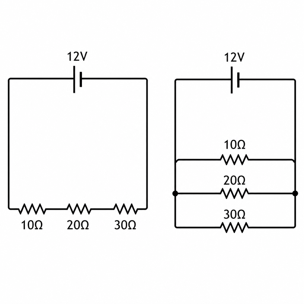
Series, Step 1: Adding the three resistances to get the total:
\[ R = 10\ \Omega + 20\ \Omega + 30\ \Omega = 60\ \Omega \]
Series, Step 2: Finding the current with Ohm's law:
\[ I = \frac{V}{R} = \frac{12}{60} = 0.2\ \text{A} \]
Parallel, Step 1: Adding the reciprocals of the three resistances:
\[ \frac{1}{R} = \frac{1}{10} + \frac{1}{20} + \frac{1}{30} \]
Parallel, Step 2: Using 60 as the common denominator and adding:
\[ \frac{1}{R} = \frac{6 + 3 + 2}{60} = \frac{11}{60} \]
Parallel, Step 3: Taking the reciprocal to get the total resistance:
\[ R = \frac{60}{11} = 5.45\ \Omega \]
Parallel, Step 4: Finding the current with Ohm's law:
\[ I = \frac{V}{R} = \frac{12}{5.45} = 2.202\ \text{A} \]
The answer can be checked another way. In parallel each branch receives the full 12 V, so the branch currents are \( \frac{12}{10} = 1.2\ \text{A} \), \( \frac{12}{20} = 0.6\ \text{A} \) and \( \frac{12}{30} = 0.4\ \text{A} \). Together they make 2.2 A. The tiny difference from 2.202 A comes only from rounding 5.45 Ω.
In series the total resistance is 60 Ω and the current 0.2 A. In parallel the total resistance is 5.45 Ω and the current 2.202 A. Changing the same resistors from series to parallel increases the current, and here it becomes about 11 times larger.
The full lesson is waiting for you
The notes are free to read in full. A free account opens the rest of the practice, and tracks your progress and confidence score for every subject. Presentations and videos need approval from Learn Yeti.